
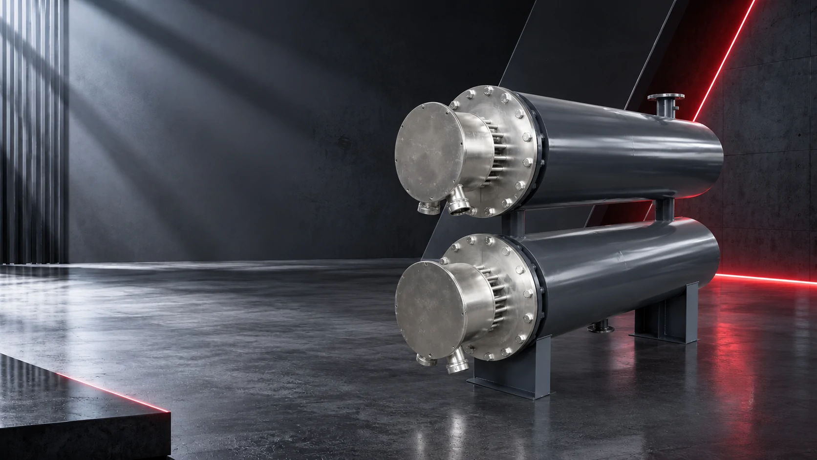
01Where the brackets go
A single fixed point
One anchor carries axial location; every other bracket slides so the line can grow freely.
Just outside the heater flanges
Put brackets on the connecting pipe, not under the heated body, so the shell is not loaded in bending.
Middle cradle when over 2 m
Beyond 2 m add a centre cradle with a resilient pad — load bearing only, never clamped.
Separate lead support
Terminal box and leads need their own bracket so their weight does not hang on the sheath exit.
02Estimating the growth
Use ΔL = α × L × ΔT: austenitic stainless α ≈ 17×10⁻⁶/°C, carbon steel ≈ 12×10⁻⁶/°C. A 2 m stainless heated section going from 20 °C to 300 °C (ΔT = 280 °C) grows about 9.5 mm; the same length in carbon steel about 6.7 mm. Plan roughly 1 cm of travel for a 2 m section.
Choose the method from the layout: natural compensation with an L or Z bend where the route allows, an expansion joint or metal hose where space is tight, and at least one flange side free to move. Draw the heated length, maximum service temperature and end fixings before specifying brackets.
03Four site mistakes
Both ends welded solid
With no sliding end the growth loads the flange face — the usual result is seepage or a cracked stub.
Clamps used as anchors
Clamping the shell looks fine cold and constrains it hot, leading to distortion and seal failure.
One-sided flange tightening
The faces tilt: pressure test passes cold, leaks appear hot. Tighten diagonally in 2~3 stages.
Ignoring insulation weight
Insulation and cladding load the cantilever, shifting the medium path and the probe position.
04What to check at commissioning
Two checks after cold installation: push the heated section by hand to confirm travel exists away from the fixed point; then, once the line is at stable temperature, scan brackets and flange rims with an infrared pyrometer. A clear hot spot means the constraint has not been released.