
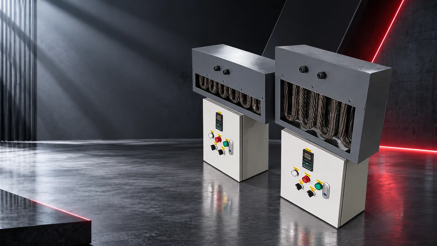
01What reheat is doing in the airway
Why it exists
A cleanroom needs a fixed supply-air temperature to hold the room, but the sensible load changes with process equipment, people and lighting. The cooling coil is sized to dehumidify; reheat trims the temperature afterwards.
Typical duty
kW = 1.20 × m³/s × 1.01 × ΔT (K) ÷ 1000 for standard air — about 1.2 kW per 1,000 m³/h per K. A 5,000 m³/h AHU reheating 8 K needs about 48 kW.
Part-load reality
The bank is sized for the worst case and runs most hours at 10-30% of that. A control method that only works at full output produces a room that hunts around its set point.
Humidity interaction
Reheat raises temperature without adding moisture, so relative humidity falls. In a room with a tight RH band, the reheat strategy and the dehumidification strategy have to be designed together.
Where the plant has a run-around or a heat pipe on the exhaust, electric reheat is often reduced by half or more. Ask what the coil leaving temperature actually is at design RH before buying the bank.
02Element construction for a hygienic airway
Sheath and fins
Stainless sheath with stainless or bare aluminium fins in a washable section; no painted or epoxy-coated fins, which chip and become particulate. Where the section is washed down, specify the ingress rating with the enclosure, not after it.
Watt density
1.5-3 W/cm² for a reheat bank at normal face velocity. Reheat rarely fails from overload; it fails from low airflow during a filter change or a fan-speed reduction.
Face velocity
Keep it between about 2 and 6 m/s across the element face. Below 2 m/s the sheath runs hot; above 6 m/s pressure drop and noise climb for no thermal benefit.
Access and cleaning
A draw-through position after the fan, with a removable section and no ledges upstream of the final filter, is what makes the bank compatible with a cleaning validation.
A reheat bank installed upstream of the fan is a recirculating contamination source with no access. Position is not an electrical decision; it is a hygiene decision.
03Control method decides the room
SCR / phase-angle power controller
Continuous 0-100% output, holds ±0.5 K with a good sensor and is the default for Grade A/B zones and for media-fill rooms.
Zero-cross / burst-fire
Fast switching with less harmonic disturbance than phase-angle; suitable for most controlled rooms, less suitable where the load is very small and continuous.
Stepped contactors
Cheap and robust, but with 25-33% steps on a 48 kW bank the room sees ±2-4 K. Acceptable in a warehouse-grade change room, not in a filling suite.
Sensor placement
In the duct after the bank, one duct length away from any bend or diffuser, and a room sensor in the cascade. A duct sensor mounted in the dead corner behind a damper reads a temperature that does not exist.
Sizing for the worst case and controlling at 15% of output is a normal reheat situation. Power controllers handle that gracefully; a two-step contactor bank does not.
04Interlocks and documentation
Airflow proving before heat, independent high-limit on the element outlet, and a trip that removes power at the contactor rather than closing a control valve. These are not optional on a duct heater, and in a validated plant they are also testable items.
What your validation team will want from the supplier: the element wiring diagram and terminal schedule, the high-limit setting and reset behaviour, the airflow range the bank was sized for, the material declarations for anything in the air stream, and the factory electrical test record. Ask for it in the inquiry, not after installation.
Where the AHU is served by a building management system, agree the control signal, the fan-status input and the alarm relay before the panel is wired. Reheat retrofits are usually a panel job, not a heater job.